Application — EMC Pre-Compliance Find the EMC problem on your bench, not in the lab.
A benchtop JRE enclosure gives you a repeatable, RF-sterile environment — −100 dB of isolation from DC to 1 GHz — so you can characterize emissions and immunity in-house, fix issues early, and walk into the compliance lab confident.
Conceptual — ambient bench RF (WiFi, cellular, Bluetooth) vs. inside a JRE enclosure (published −100 dB isolation, DC–1 GHz).
- ISOLATION −100 dB
- DC–1 GHz
- VERIFIED WITH TVK-2
Every problem you catch on the bench is one you don't catch at the lab.
A failed compliance run is not just a fee — it is a rebook, a redesign loop, and weeks of schedule. The point of pre-compliance is to compress that loop onto your own bench.
- Fee
- Rebook
- Redesign loop
- Isolate
- See only your signals
- Iterate
A benchtop enclosure will not replace the accredited chamber for your final certification report. What it does is let you develop and debug against a clean, repeatable baseline so that when you do book the lab, you are confirming a pass — not discovering a fail.
Isolation you can plan around.
- Standard JRE enclosure — published minimum
Published minimums: −100 dB to 1 GHz, −95 dB to 3 GHz, −85 dB to 6 GHz. For scale: a GPS receiver operates at −130 dBm. Drag the trace to read the published minimum at any cited frequency.
| Frequency | Standard JRE enclosure — published minimum |
|---|---|
| 10 MHz | ≥100 dB |
| 1 GHz | ≥100 dB |
| 3 GHz | ≥95 dB |
| 6 GHz | ≥85 dB |
Isolation is set by the weakest link, not the enclosure walls.
80 dB is a 100,000,000-to-1 power ratio. With receivers that work at −85 dBm or lower, every detail matters — cable position, shielding quality, connector torque, foam placement.
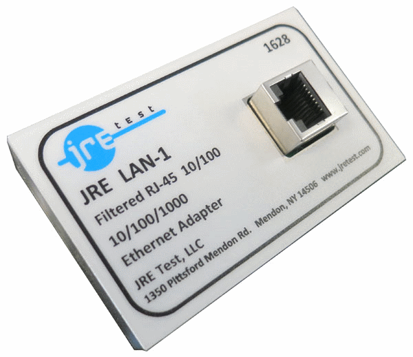
Each filtered path adds ~3 dB of leakage per doubling (10·log₁₀N). Configure the I/O plate with only the interfaces you need, use shielded cables, and a piece of absorber foam near the plate can recover 10 dB or more.
What the bench setup buys you.
Your bench is full of ambient RF — WiFi, cellular, Bluetooth, switching-supply noise — so you can't tell whether an emission is your DUT or the room.
Inside the enclosure, the only signals the device sees are the ones you present. A 100 dB-isolated DC–1 GHz environment isolates the DUT, so you measure its behavior, not the building's.
Results that don't repeat are useless for debugging a marginal EMC issue.
A fixed I/O plate, fixed cable routing, and a benchmarked setup give you the same coupling path every run. You compare design revisions against each other, not against a moving room.
You suspect a shielding or seam problem but can't see where it's leaking.
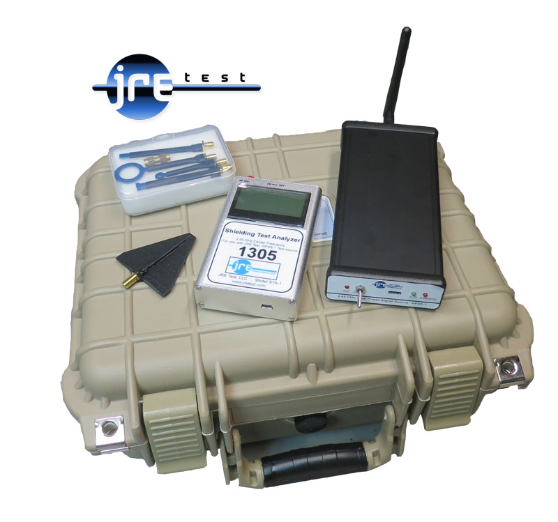
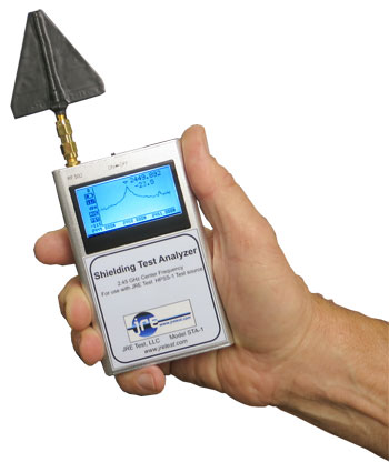
Verify isolation in-house with the TVK-2 kit: the HPSS-1 source plus the STA-1 analyzer and near-field probes let you read overall isolation and pinpoint the leak at a seam or I/O screw.
A bench EMC starting point
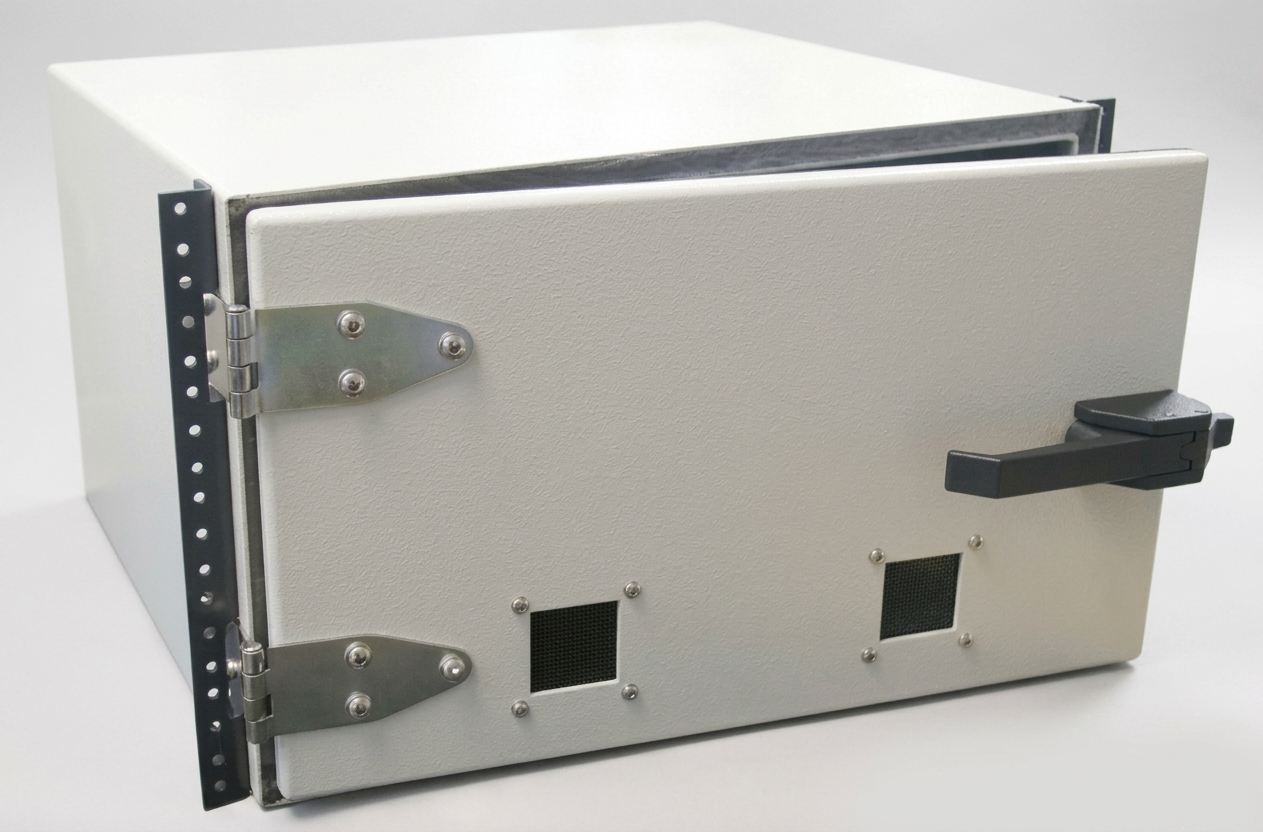
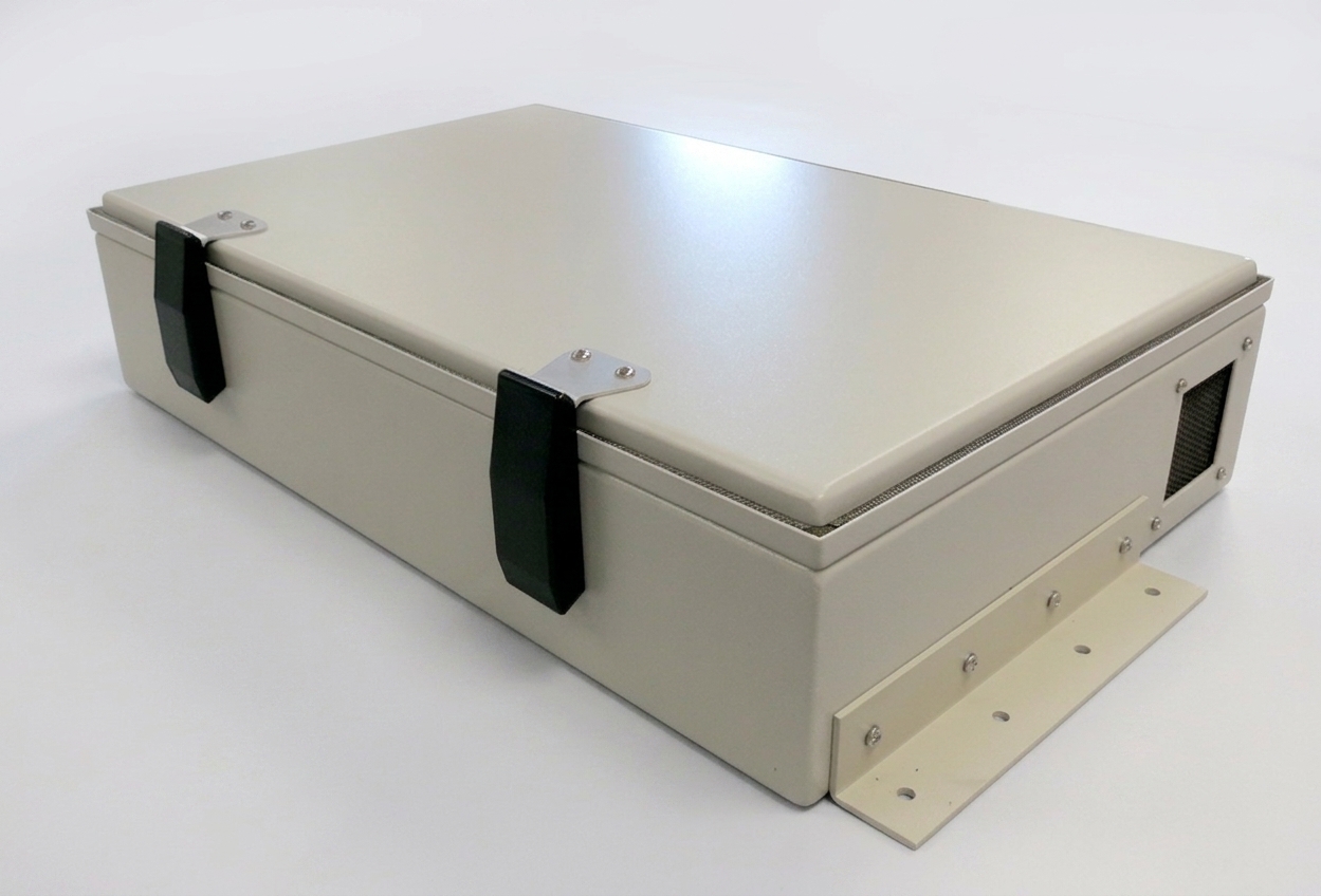
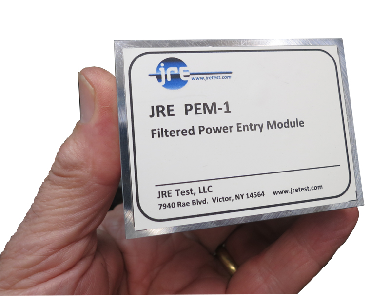
Every price published. Pick an enclosure, the filters your DUT needs, and a way to verify the shielding — on one combined inquiry.
-
-
-
-
-
-


Frequently asked questions
No. It gives you a clean, repeatable baseline for development and debugging before the final certification run at an accredited lab.
The TVK-2 uses the HPSS-1 source with the STA-1 analyzer and near-field probes. It can show the overall isolation and help locate leakage at a seam or I/O screw.
System isolation is set by the weakest link, and each filtered path adds leakage. A fixed plate with only the required interfaces also makes cable routing and the coupling path easier to repeat from run to run.
Go deeper — engineering guides
- Measuring and verifying shielding isolation How to test the test chamber with the TVK-2 — overall isolation by Yagi, leak-hunting with E- and H-field probes.
- The effect of adding multiple I/O filters The weakest-link principle, the 3 dB-per-doubling table, and proven techniques to recover isolation.
- Taking the mystery out of RF wireless testing The overview: why a shielded chamber is needed, the −100/−95/−85 dB spec, absorber foam and verification.
- The RF absorbing foam inside your test chamber Why the foam is the damper and not the shield — 40 dB per wall bounce, and why a bare box gives you unrepeatable readings.
Build your pre-compliance bench.
Tell us the device and the standards you're chasing — we'll spec the enclosure, filters and verification kit and quote it. Anything from the catalog, including the I/O plates we configure for you, builds and ships in 3 to 4 days. A ground-up custom enclosure built to your own dimensions runs 12 to 16 weeks plus a one-time engineering charge.