
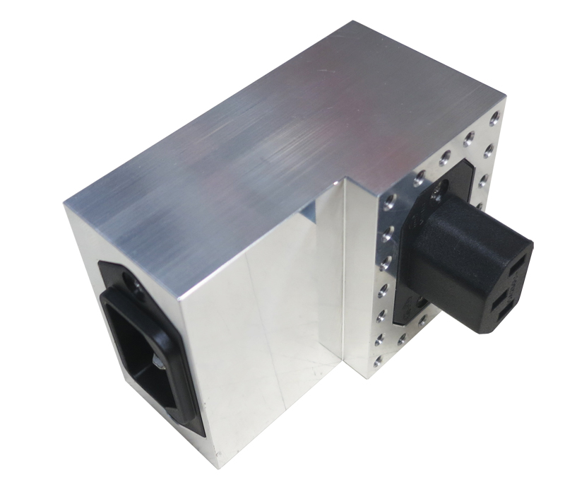
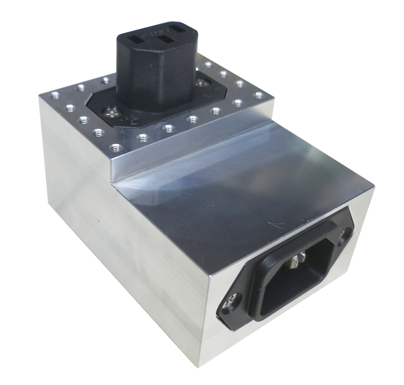
Filtered Power Entry Module — JRE PEM-1
Filtered IEC C14-to-C13 AC power entry rated for 120/240 VAC at 10 Amps, with 80 dB test-system isolation.
JRE PEM-1 specifications
- Outside dimensions
- 3" H x 2.25" W x 1.6" D (76 x 57 x 41 mm)
- Isolation
- 80 dB isolation in test system configuration
- Power
- 120/240 VAC 50/60 Hz 10 Amps
- Connector Outside
- IEC 60320 C14 Male
- Connector Inside
- IEC 60320 C13 Female
- Power capability
- 120/240VAC 50/60Hz 10A
- Earth leakage (120VAC/60Hz)
- ≈136 µA
- Earth leakage (240VAC/50Hz)
- ≈226 µA
- Surge protection
- 480VAC MOV
- Housing
- Rugged machined-aluminum
- Mounting screws
- 4-40 (included)
- Clearance hole size
- 0.1285" diameter - #30 or 3.3mm drill
JRE PEM-1 overview
Wall-powered DUTs need a practical way to receive mains power without letting the power lead become an RF path. I recommend the JRE PEM-1 when familiar IEC connections are wanted on both sides of the shield wall.
- 120/240 VAC, 50/60 Hz power entry rated to 10 Amps
- IEC 60320 C14 Male connector outside and C13 Female connector inside
- 80 dB isolation in the complete test-system configuration
- Approximately 136 µA earth leakage at 120 VAC/60 Hz
- Approximately 226 µA earth leakage at 240 VAC/50 Hz
- 480VAC MOV surge protection for line-transient control
- Machined-aluminum housing measuring 3" H x 2.25" W x 1.6" D (76 x 57 x 41 mm)
- Included 4-40 mounting screws; $289.00 price and in-stock status
I pair the PEM-1 with a matching JRE outlet strip when the internal power distribution should arrive as a turnkey assembly. Bought alone, it ships with a mating C13 cord connector for the chamber side. The IEC format accepts local cordsets, so the same module can move between mains standards without changing the filtered entry.
Go deeper
Used in: EMC Pre-Compliance · Defense & Security
- Measuring and verifying shielding isolation How to test the test chamber with the TVK-2 — overall isolation by Yagi, leak-hunting with E- and H-field probes.
- The effect of adding multiple I/O filters The weakest-link principle, the 3 dB-per-doubling table, and proven techniques to recover isolation.
- Taking the mystery out of RF wireless testing The overview: why a shielded chamber is needed, the −100/−95/−85 dB spec, absorber foam and verification.
- The RF absorbing foam inside your test chamber Why the foam is the damper and not the shield — 40 dB per wall bounce, and why a bare box gives you unrepeatable readings.
I/O Interfaces nearest the JRE PEM-1


Tell us what connections your device needs.
Tell us what connections you need to your device under test — USB, Ethernet, RS-232, RF connectors, etc. We'll spec it out with you. No cart, no checkout: you send an inquiry and we quote it.
Ask an Engineer