More and more devices today contain RF wireless circuitry — from the obvious, like cell phones and laptops, to the less obvious, like car key fobs, smart thermostats, Bluetooth-enabled medical devices, and IoT sensors embedded in industrial equipment. These devices communicate over the open airwaves, and their operation depends upon careful design of operating frequency, power level, modulation format, and protocol. Since these devices are wireless, testing them presents a unique challenge: the signals propagate without any physical means of connection, and your lab is full of other signals doing the same thing.
The Problem: Your Lab is Not Quiet
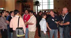
Imagine yourself in a large meeting room with hundreds of people milling about — many groups conversing loudly, some holding quieter personal conversations. The human ear and brain, being an incredible signal processing system, can in many cases pick out your conversational partner from amid this room of noise. But how many times have you struggled to understand what someone said, or asked them to repeat themselves? Now imagine trying to precisely measure the volume of your partner's voice while everyone else is talking.
This is exactly the situation your wireless device faces in an unshielded lab. When you are testing a Bluetooth module on your bench, can you be certain the device is hearing only your test signal? Or is it also seeing the WiFi router in the corner, the microwave oven in the break room, the Bluetooth headset left powered on in a desk drawer, cell phone handshakes from phones in the building, or the device on the bench across the lab? Unless you can reliably isolate your device from all other RF signals in the environment, you cannot test with any confidence in your results.
This problem has only gotten worse over time. When RF wireless testing first became common, the ambient RF environment in a typical lab was relatively sparse. Today, any given location is flooded with WiFi (2.4 and 5 GHz, and now 6 GHz with WiFi 6E), Bluetooth and BLE, cellular signals across multiple bands from 700 MHz to millimeter wave, Zigbee, Z-Wave, LoRa, NFC, UWB, and more. The RF noise floor in a modern lab or office building is dramatically higher than it was even ten years ago.
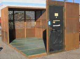
The Traditional Solution: Screen Rooms
Historically, screen rooms — also known as Faraday cages or shielded rooms — were used to provide a clean RF environment for testing. These rooms are large enough to enclose the entire lab bench, all test equipment, and the operator. In the past, when RF wireless was less ubiquitous, these expensive installations were a reasonable solution. But a screen room is a major capital investment, requires dedicated floor space, and is fixed in place. For organizations where RF testing is one of many activities rather than the sole purpose of the facility, a screen room is often impractical.
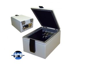
The Modern Solution: Benchtop RF Shielded Test Enclosures
For the vast majority of RF wireless tests, a benchtop RF shielded test enclosure is a better solution. It sits on your bench, provides the same clean and sterile RF environment as a screen room, and costs a fraction of the price. The device under test goes inside the enclosure, the lid is closed, and the outside world disappears. The only signals the device sees are the ones you intentionally present to it through filtered or shielded connections, and nothing the device emits can leak out to interfere with other tests or equipment in the lab.
All standard JRE Test enclosures provide a minimum of -100 dB shielding isolation from DC to 1 GHz, -95 dB to 3 GHz, and -85 dB to 6 GHz. To put that in perspective, -100 dB means the signal inside the chamber is attenuated by a factor of 10 billion before it reaches the outside — for all practical purposes, the device is invisible to the outside world, and the outside world is invisible to the device. For testing at 5G and microwave frequencies up to 28 GHz, an optional MW upgrade extends shielding isolation to greater than -85 dB across the entire range. (For more on microwave-frequency testing, see our whitepaper: Using an RF Test Chamber at 5G and Microwave Frequencies.)
Getting Signals In and Out: The Shielding Barrier
Now that we have a sterile RF environment, how do we get our test signals into and out of it? Every connection that crosses the enclosure wall — the shielding barrier — must be handled correctly, or the isolation we just established will be compromised. There are several categories of connections to consider.
RF Test Signals
For injecting an RF stimulus from an external signal generator or observing your device's output on a spectrum analyzer, simple bulkhead RF connectors penetrate the enclosure wall. These are intentionally unfiltered — you do not want to impede the test signal in any way. The coaxial cable's own shielding remains continuous from the external equipment, through the bulkhead connector in the enclosure wall, and into the chamber, maintaining isolation from external interference. SMA, BNC, and Type N bulkhead connectors are the most common; for microwave frequencies, 2.92 mm (K-type) connectors rated to 40 GHz are available.
Over-the-Air Testing with Antennas
Many devices communicate wirelessly and cannot be connected directly via coaxial cable — WiFi modules, Bluetooth devices, cellular handsets, RF key fobs, and similar products must be tested over the air. In these cases, an antenna inside the enclosure radiates or receives the test signal, connected to ext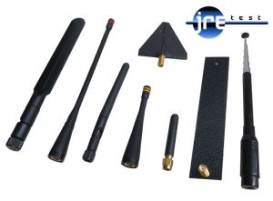 ernal equipment through a bulkhead SMA connector on the I/O plate.
Inside a small enclosure, antennas operate in the near field and do not exhibit their published free-space characteristics. This is completely normal and does not prevent you from performing valuable, repeatable tests. The key is benchmarking: test a known-good "gold standard" device, record the results, and measure all subsequent devices against that benchmark. We offer a selection of antennas designed for use inside test enclosures, including the BBA-1 ultra-wideband (1 MHz to beyond 6 GHz) and band-specific antennas for WiFi/Bluetooth and cellular frequencies.
For a detailed discussion of antenna behavior inside test enclosures — including measured path loss data — see our whitepapers: How to Radiate Signals Into and Out of an RF Shielded Test Enclosure Using Antennas and Understanding Antenna Performance Inside an RF Shielded Test Enclosure.
Power Connections
If your device requires external power inside the chamber, the power lines must be filtered to prevent conducted RF from entering or exiting on the power cable — unfiltered power lines will bypass the chamber's shielding entirely. The JRE PEM-1 filtered power entry module provides 80 dB attenuation of conducted RF on AC mains power using high-performance feedthrough capacitors and broadband inductors. For DC power, terminal strip mounted feedthrough filters using a Pi-style topology (two capacitors with a series inductor) provide 60 to 75 dB of filtering at VHF and above.
Data Connections: The Filtering Challenge
This is where things get interesting, because the signals you need to pass to your device often occupy the same frequency range as the RF interference you are trying to keep out. The fundamental challenge is filtering out real-world RF while allowing your data signals through unimpeded.
For lower-speed data — RS-232, audio, simple control lines, thermocouples — a capacitive feedthrough filter such as a filtered DB-9 connector works well. The capacitance value determines the tradeoff between RF filtering and data signal loading. To illustrate: consider 9600-baud RS-232 data, which produces a seria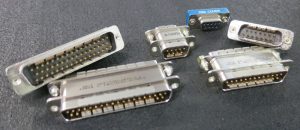 l data stream at approximately 19.2 kHz. A 1000 pF feedthrough capacitor presents an impedance of about 8.3 kilohms at this frequency (capacitive reactance = 1 / (2π × 19,200 × 1000 × 10⁻¹²)). This loading is negligible — the data passes through essentially unaffected, while RF signals at much higher frequencies see a very low impedance path to ground and are effectively shorted out. We offer DB connectors in 1000 pF (suitable for data rates up to about 10 Mbps), 100 pF (up to about 100 Mbps), allowing you to select the best tradeoff for your application. In general, use the most capacitance your data speed will tolerate — more capacitance means better RF filtering.
But what about high-speed data where the data rates fall squarely within the RF frequency range? USB 2.0 operates at 480 Mbps, USB 3.0 at 5 Gbps, 10GBASE-T Ethernet at 10 Gbps, and Thunderbolt at up to 40 Gbps. At these speeds, simple capacitive filtering cannot distinguish between the data and the interferenc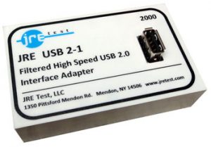 e — both are RF signals. A low-pass filter that blocks interference at 2.4 GHz would also destroy your 5 Gbps USB 3.0 data.
This is where JRE Test's patented filtering technology comes in. For USB 2.0, the JRE USB 2-1 uses a low-pass filter design that passes all USB 2.0 data while filtering frequencies above 700 MHz by over 60 dB. The connection is fully conductive, allowing compliant USB enumeration and handshaking — something not possible with fiber optic alternatives.
For faster data — USB 3.0, USB-C, 10GBASE-T Ethernet, and HDMI — low-pass filtering simply cannot work, because the data frequencies overlap with the interference frequencies. JRE Test developed and patented a fundamentally different approach: signal phasing techniques that exploit the difference between the balanced differential data signals (which are what you want) and the common-mode RF interference (which is what you want to reject). This patented technology allows our USB 3-1, USB-C, LAN-10G, and HDMI filters to provide excellent RF isolation even when the data rates fall within the same frequency range as the interfering signals. There is no upper frequency limit on these filters — they do not use low-pass filtering at all.
For a deeper discussion of data filtering tradeoffs, see our whitepaper: Understanding Data Signals Through Filtered I/O Connectors. For USB-C and Thunderbolt-specific considerations including cable length and active cable guidance, see: USB-3 and USB-C Special Considerations.
Taming Reflections: RF Absorbing Foam
Signals inside the test chamber need to be damped to reduce RF reflections and standing waves that can affect device behavior. Think of a room where every surface is hard — bare walls, concrete floor, no curtains or furniture. Put a group of children in that room with a few televisions turned up loud and the noise reverberates off every surface, creating a cacophony of reflected sound. Now picture the same room with carpet, acoustic ceiling tiles, and upholstered furniture. Even though the children are still making the same noise, the room is far quieter because the soft surfaces absorb the reflections rather than bouncing them back.
This is exactly what RF absorbing foam does inside the test chamber. The metallic walls of the enclosure are excellent reflectors of RF energy. Without absorbing material, signals would bounce back and forth between the walls, creating standing waves and unpredictable hot spots and nulls inside the chamber. JRE Test lines all enclosures with LS-30 RF absorbing foam (3/4 inch on all models except the compact JRE 0709-P, which uses 1/2 inch) that provides over 40 dB of round-trip reflection attenuation. For applications requiring even more absorption at lower frequencies, an optional low-frequency absorber (SB036-040) can be added for an additional approximately 50 dB of round-trip reflection attenuation.
Thermal Management
The inside of a test enclosure is a sealed environment with limited natural airflow. For most test scenarios — where the device spends a relatively brief time inside and generates modest heat — this is not a concern, since opening the lid between test cycles allows internal temperature to equalize rapidly. However, for devices that dissipate significant power or for extended test runs with the lid closed, heat removal must be addressed.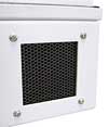
JRE Test enclosures use high-performance mil-spec rated honeycomb waveguide vents that allow smooth airflow while maintaining full shielding isolation — greater than 100 dB at 1 GHz and greater than 95 dB at 10 GHz. These are not simple metallic screening; the hexagonal cell geometry acts as a waveguide beyond cutoff, providing excellent RF attenuation while offering minimal resistance to airflow. For active cooling, RF shielded fans are available that mount directly into the chamber wall, powered by an independent filtered external supply that is completely separate from the I/O plate and will not introduce noise onto your device's power rails.
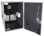
The I/O Plate System: Built for Flexibility
To be truly useful, a test enclosure must be easy to configure and reconfigure. Having the correct connectors already installed makes the job easier, but it also avoids RF leakage problems that can arise from chains of coaxial adapters and jury-rigged connections.
Every JRE Test enclosure uses a standardized, removable I/O plate system. There are four plate sizes across the entire product line (A, B, C, and D), and these plates are field-repla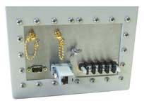 ceable with simple hand tools. A single enclosure with a few spare I/O plates, each configured for a different test scenario, can serve many different projects over its lifetime. The plates are CNC machined and can accommodate dense connector layouts — C-size plates (7 x 7 inches) have been built with over 30 SMA bulkheads on a single plate. Custom plates typically take 3 to 5 days and cost $100-150 for the plate itself, plus connectors.
This system is something I developed over 40 years ago when I founded Ramsey Electronics, and it remains one of the most practical features of our enclosures. Rather than modifying and drilling the actual enclosure body for each customer's configuration — imagine trying to punch connector patterns on an ungainly metal box — we customize a flat plate, install it, and final-test the chamber in the exact configuration you will be using. If your test requirements change a year later, you swap the plate. The chamber never becomes obsolete.
For more on selecting the right enclosure and configuring your I/O, see our whitepaper: How to Select and Configure an RF Shielded Test Enclosure.
Maintaining Shielding Integrity Over Time
Since the enclosure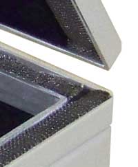 is a mechanical device, it is subject to wear — particularly on the mating RF gasketed surfaces where the lid meets the body. JRE Test uses rugged knitted-mesh stainless steel or Monel gaskets on a long-life neoprene core. These gaskets a
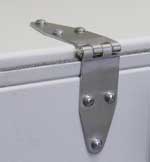 re rated for tens of thousands of compression cycles, but are easily and inexpensively replaced when needed — we recommend replacement after approximately 20,000 lid cycles or once a year, whichever comes first. Oversized stainless steel hinges contribute to long life and better shielding effectiveness by minimizing free travel and bearing play. Many JRE enclosures also feature adjustable latches that allow you to increase compression on the gasket as it wears, maintaining a tight seal without replacing the gasket.
Verifying Your Shielding: The JRE Test Verification Kit
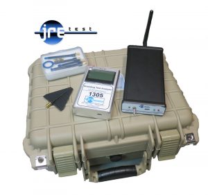
How do you know your enclosure is still performing to specification? JRE Test is the only enclosure manufacturer that produces a purpose-built RF test chamber verification kit. The JRE HPSS-1 is a high-power 2.45 GHz synthesized signal source in a Li-Ion battery powered enclosure with a dipole antenna. Place it inside your test chamber, close the lid, and use a high-gain Yagi antenna outside to "sniff" for RF leakage around the enclosure's seams, door gasket, I/O plate, and ventilation ports. Using a spectrum analyzer or the JRE STA-1 handheld spectrum analyzer, you can easily measure RF isolation greater than 110 dB. The complete JRE TVK-2 test verification kit includes both the HPSS-1 and STA-1 along with antennas, chargers, and a carry case.
This is also an excellent tool for identifying leak paths in walk-in shielded rooms — door seal degradation, unsealed penetrations, and conducted emissions on power or signal lines all become visible when you have a known signal source inside and a calibrated receiver outside.
Watch this video to see the verification process in action:

For more detail on measurement methodology, see our whitepaper: Measuring and Verifying the Shielding Isolation of an RF Shielded Test Enclosure.
Where to Go From Here
If you are new to RF shielded test enclosures, the next step is to determine what you need to test and what connections your device requires. Our whitepaper How to Select and Configure an RF Shielded Test Enclosure walks through the selection process step by step, and our Configuration Worksheet (PDF) is a handy tool for organizing your I/O requirements.
Browse our complete enclosure catalog to see all 21 standard sizes, explore our full range of I/O interfaces, or visit the Resources page for all of our technical whitepapers. All standard enclosures are in stock and can ship within days of your order — all we need to know is the configuration you require.
If you have questions, contact us. We have configured thousands of test chambers for customers in over 30 countries, and we are happy to help you get to the right solution.