A practical guide from the engineers who invented the benchtop RF test chamber — covering enclosure sizing, I/O configuration, filtering, power, thermal management, and antenna selection.
Start with the Device
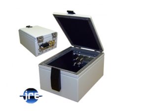
The first decision is mechanical: your test enclosure must comfortably contain the device under test (DUT) along with all associated cables, adapters, and connections. This sounds obvious, but I have seen many customers underestimate the space required once cables are plugged in and routed with proper bend radius. A device that measures 6 inches on the bench can easily become 10 or 12 inches once you account for USB cables, RF adapters, power cords, and antenna clearance.
My advice: gather all the components you plan to use — the device, every cable, every adapter, any battery pack or power supply that will live inside the chamber — connect them on the bench, and measure the actual footprint. Add at least an inch of clearance on every side. If you are using antennas inside the chamber, you will need additional space for antenna placement and separation from the DUT.
Practical tip: Consider future "product creep." If you are developing a product line, the next revision may be larger. It is often more economical to buy a slightly larger enclosure now than to buy a second one later. The I/O plates are easily swapped in the field, so the same enclosure can be reconfigured for many different test setups over its lifetime.
JRE Test maintains a large inventory of 21 standard enclosure sizes, ranging from the portable JRE 0709-P (ideal for cell phones and dongles) to the large JRE 3036 (which can house entire computer systems). All standard chambers are in stock and can ship within days of your order. Our model numbers reflect the approximate outside dimensions in inches — the first two digits are the width, the second two are the depth — so a JRE 1714 is approximately 17 inches wide by 14 inches deep.
If none of our standard sizes fit your application, we can modify an existing enclosure or design a fully custom chamber. Bear in mind that custom work involves engineering charges (typically around $3,500 NRE) and longer lead times (12–16 weeks), so I always recommend looking at the standard lineup first.
The I/O Plate System
This is one of the most important things to understand about JRE Test enclosures, and it is the feature that gives our chambers their extraordinary flexibility.
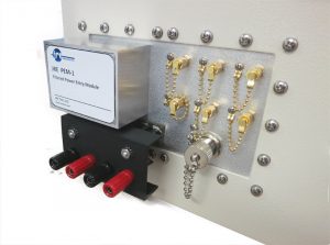
Every JRE Test enclosure uses removable I/O plates — flat metal panels that mount into the enclosure wall and carry all of your filtered connectors and interfaces. I originated this concept over 40 years ago when I founded Ramsey Electronics, and it remains the core of our design philosophy. The idea is simple: we stock a large inventory of finished enclosures, and we customize each one by machining and populating an I/O plate specific to the customer's needs. This avoids modifying the actual enclosure body — imagine trying to drill holes and punch connector patterns on an ungainly metal box.
There are four I/O plate sizes across the entire product line:
| Plate size | Dimensions | Used by |
| A-size | 2.75″ × 6″ | JRE 0709-P, 1618, 2214 |
| B-size | 4.5″ × 7″ | JRE 0912, 1812, 1812F, 1812WS, 2218 |
| C-size | 7″ × 7″ | JRE 0814, 0814-2R, 1522, 1714, 1720, 1724B, 2220A, 2233, 2525, 2830, 3036 |
| D-size | 4″ × 6″ | JRE 1724A, 1729A |
Many of our larger enclosures have two or even three I/O plates, giving you significant connector capacity. A single C-size plate can accommodate a surprising number of connectors — we have built plates with over 30 SMA bulkheads.
The plates are recessed into the chamber wall and do not intrude into the internal test volume. They are field-replaceable with simple hand tools, so one enclosure with multiple I/O plates offers a world of testing possibilities. There is no harm in adding extra interface connectors that you may potentially use later — unused, properly sealed connectors do not degrade shielding isolation.
To speed your delivery, we offer a selection of pre-populated I/O plates with the most common connector and interface filter configurations. You may find one perfectly suited to your needs and be testing in just days.
Here is a handy worksheet you can download to help organize your connector and filter requirements: Configuration Worksheet (PDF)
Critical: Every penetration must be filtered Any unsealed or unfiltered penetration through the enclosure wall will destroy your shielding isolation, especially at higher frequencies. At 6 GHz the wavelength is about 50 mm — even small gaps become significant. At 40 GHz the wavelength is about 7.5 mm, and the tiniest opening is a wide-open window for RF energy. Never drill holes, use copper tape patches, or bolt on unfiltered cover plates. All wiring must pass through properly filtered feedthroughs on the I/O plate.
Shielding Isolation — What to Expect
All standard JRE Test enclosures provide the following shielding isolation:
- −100 dB from DC to 1 GHz
- −95 dB to 3 GHz
- −85 dB to 6 GHz
This is the isolation of the enclosure itself with a properly sealed, blank I/O plate installed. Once you add filtered I/O interfaces, the overall system isolation is determined by the weakest link — typically the I/O filters, not the enclosure. Each filtered interface has its own isolation specifications listed on its product page. In practice, properly configured systems achieve well in excess of 80 dB of isolation across their operating range. For a deeper look at how multiple I/O filters affect overall isolation, see The Effect of Adding Multiple I/O Filters to a Test Enclosure.
5G and microwave frequencies
For testing above 6 GHz — increasingly common with 5G, millimeter-wave, and radar applications — we offer a Microwave (MW) upgrade that extends shielding isolation to greater than 85 dB out to 28 GHz. This upgrade adds $480 to the enclosure price and includes conductive fabric gasketing on the I/O plate, as well as added RF absorbent foam on the door for enhanced high-frequency sealing. When using the MW upgrade, your I/O filters should also be MW-rated (additional $80 per filter section) to ensure the filters do not become the weak link at these higher frequencies. For more detail, see Using an RF Test Chamber at 5G and Microwave Frequencies.
Data Connections
This is where it gets interesting, and where I spend most of my time helping customers get their configurations right. The challenge is straightforward: you need to pass data signals across the shielding barrier while filtering out unwanted RF interference. The difficulty is that modern high-speed data signals occupy the same frequency range as the RF signals you are trying to keep out.
JRE Test offers the industry's widest selection of filtered data interfaces, and several of our designs are covered by US patents. Here is how to think about each one:
USB
We offer three USB filtered interfaces, each designed for a specific speed tier:
- JRE USB 2-1 ($369) — USB 2.0 High Speed. Uses a low-pass filter design that passes data up to 480 Mbps and stops RF above approximately 700 MHz. This is the right choice for USB 2.0 devices.
- JRE USB 3-1 ($480) — USB 3.0 SuperSpeed. At 5 Gbps data rates, the signal frequencies overlap with common wireless bands, so low-pass filtering would kill your data along with the interference. This filter uses our patented signal phasing technique that discriminates between the desired data signals and unwanted RF interference based on signal balance. Requires good quality, properly shielded cables.
- JRE USB C-1 ($549) — USB Type C SuperSpeed. Similar patented design for USB-C applications. Completely passive — no active electronics inside. The filter electrically "looks like" approximately 1 to 1.5 meters of additional cable in the signal path.
USB-C and Thunderbolt speed guidance: The USB-C filter works with USB-C, USB4, and Thunderbolt — the connectors are physically identical regardless of speed revision. With the supplied short jumper cables, the filter reliably passes 5 Gbps and often up to 10 Gbps depending on device robustness. For faster speeds (20 Gbps, Thunderbolt 40 Gbps), use an active cable on the external side to compensate for the equivalent cable length of the filter. The USB/Thunderbolt protocol will automatically negotiate down to a supportable speed if cable attenuation is too high — this is a feature of the protocol, not a defect. For full details, see USB-3 and USB-C Special Considerations.
Ethernet
- JRE LAN-1 ($435) — RJ-45 Ethernet 10/100/1000. Low-pass design that passes all standard Ethernet signals and rejects cellular, LTE, and WiFi frequencies above 700 MHz. Over 80 dB attenuation above 1 GHz with flat response below 480 MHz.
- JRE LAN-10G-1 ($545) — RJ-45 10GBASE-T Ethernet. Uses our patented signal phasing technique (same principle as the USB 3 filters) to discriminate data from interference at overlapping frequencies. Designed exclusively for 10GBASE-T (copper twisted pair, RJ-45). Works best when connected devices and cables maintain a high degree of balance.
We also offer combination filters — LAN + USB combos — on a single interface housing, which saves I/O plate space and cost when you need both.
HDMI
The JRE HDMI-1 ($480) is fully compliant with HDMI version 1.4 and higher. For higher HDMI versions and speeds, use an active HDMI cable. The filter uses our patented signal phasing technique.
Serial data, control lines, and other signals
For lower-speed signals such as RS-232, RS-485, audio, thermocouple lines, CAN bus, or simple control signals, we offer several options:
- Filtered DB connectors (DB9, DB15, DB25) — Pi-style feedthrough capacitor filters on each pin. Available in 1000 pf (best RF filtering, supports up to ~10 Mbps) and 100 pf (good filtering, supports up to ~100 Mbps). The capacitance choice determines the tradeoff between filtering performance and data speed. See Understanding Data Signals Through Filtered I/O Connectors for more detail on this tradeoff.
- Filtered terminal strips — 2500 pf feedthrough filtering, rated at 250 VAC / 100 VDC at 20 amps. Pi-style filter providing 60–75 dB of filtering at VHF and above. Screw terminals on the outside, push-on terminals on the inside, or also available with banana jacks. Available in 2, 4, and 6 terminal configurations.
- JRE UFI-1 ($445) — Universal Filtered Interface with 8 independent filtered lines. Extremely versatile for thermocouples, CAN, RS-232/485, audio, automotive Ethernet, and other specialized signals.
Fiber optic
Fiber optic connections provide ultimate RF isolation since there is no electrical conductor to carry interference. We offer fiber pass-through portals (JRE FPT for up to 5 cables, rated to 6 GHz) and precision machined fiber bulkheads (Fiberplex WGF-6 for up to 6 cables, rated to 28 GHz). FC Simplex and ST Multimode bulkhead connectors are also available.
RF Signal Connections
When you need to present your device with a stimulus RF signal or observe an RF signal from the device, you use standard coaxial bulkhead connectors through the I/O plate. There is no RF filtering on the coaxial path — you do not want to impede the signal in any way. The shielding of the coaxial cable remains continuous from the external test equipment, through the enclosure wall, and into the chamber, maintaining proper isolation from external signals.
We stock a wide variety of bulkhead feedthrough connectors:
- SMA — the most common, good to 18+ GHz
- 2.92 mm (K-type) — rated to 40 GHz, for microwave applications
- BNC, N-type, TNC, UHF, SMB — for various applications and frequency ranges
All bulkhead feedthroughs present the same connector type on both sides of the I/O plate. If you have a different or proprietary RF connector, a suitable adapter can usually be found.
Antennas and Over-the-Air Testing
Many tests require radiating a signal to the device or receiving a signal from it using antennas inside the chamber. This is perfectly viable inside a test enclosure, but there are a few things to understand.
Inside a small enclosure, antennas operate in the near field — generally within about 10 to 50 wavelengths of the antenna. In this region, the antenna's characteristics are significantly affected by nearby objects, whether conductive or nonconductive. The E and H fields get out of sync and cannot form a proper electromagnetic wavefront the way they would in free space. This is completely normal and expected.
The good news is that in a small enclosure, the antenna and the DUT are close together, so there is plenty of signal strength to overcome any near-field perturbations. You can absolutely perform valuable, repeatable tests. The key is to not try to relate your measurements 100% to free-space conditions. Instead, use a properly operating device as a "gold standard," note its measurements in your specific test setup, and benchmark subsequent devices against it.
JRE Test offers several antenna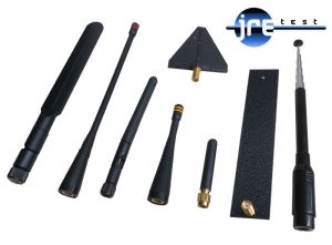 s designed for use inside test enclosures:
- JRE BBA-1 ($150) — Ultra wideband, 1 MHz to 6+ GHz. This is a "lossy" antenna by design, providing about 20–30 dB less gain than a matched quarter-wave. The lossiness is a feature: it makes the antenna less affected by its environment inside the chamber, and it maintains excellent VSWR across the entire frequency range. When your external signal generator needs a good match and the DUT inside may be moving around or affecting the antenna, the BBA-1 is the right choice.
- JRE ANT-82 ($44) — Multiband cellular/PCS blade, 700–4900 MHz.
- JRE ANT-211 ($78) — Broadband log periodic, 2–11 GHz.
- JRE ANT-245 ($23) — Dipole for 2.4 and 5–6 GHz WiFi/Bluetooth.
All antennas use SMA connectors and connect to an SMA bulkhead feedthrough on the I/O plate. For a detailed discussion of how to set up antenna-based testing, see How to Radiate Signals Into and Out of an RF Shielded Test Enclosure Using Antennas.
Power Considerations
If your device needs power inside the chamber, that power connection must be properly filtered as it crosses the enclosure wall. Unfiltered power cables are one of the most common sources of RF leakage into (or out of) a test chamber.
AC power
The JRE PEM-1 ($249) is a filtered power entry module using an IEC C13/C14 connector rated at 10 amps (1,200 watts). This is more than sufficient for virtually any test chamber application — the actual power consumption inside a chamber is typically a few hundred watts at most. The PEM-1 uses high-performance feedthrough capacitors and broadband inductors to provide 80+ dB attenuation of any RF signals conducted on the power cable. An AC outlet strip can be added inside the chamber for convenient power connections to your device.
DC power
For DC power connections, filtered terminal strips are the most common solution. These pi-style feedthrough filters provide 60–75 dB of filtering at VHF and above, rated at 250 VAC / 100 VDC at 20 amps. Available in 2, 4, and 6 terminal configurations. Filtered banana jack versions are also available if you prefer binding post connections — the RF performance is identical, the difference is just connection style.
Thermal Considerations
The inside of a test enclosure is a closed volume with limited convection. In most cases this is not an issue — opening the lid to insert a device allows internal air temperature to equalize rapidly. However, if your DUT generates significant heat, you will need ventilation.
Many JRE Test enclosures include honeycomb waveguide vents as standard, providing airflow while maintaining full shielding isolation. For active cooling, we offer RF shielded fans ($95 each) in several sizes that mount directly into the chamber walls. These fans are powered by an independent filtered external power supply and are completely separate from the I/O plate — they will not introduce noise to your DUT power rails. Shielding isolation through the honeycomb vent is maintained at greater than 100 dB at 1 GHz and greater than 95 dB at 10 GHz.
RF Absorbing Foam
All JRE Test enclosures are lined with LS-30 RF absorbing foam (3/4 inch thick on all models except the JRE 0709-P which uses 1/2 inch). This foam provides over 40 dB of "round trip" attenuation, meaning signals reflecting off internal surfaces are significantly damped. The foam is rated to 90°C with a UL 94V-0 flammability rating.
For applications requiring additional or different internal absorption, contact us with details so we may assist.
Putting It All Together — Your Selection Checklist
Here is a summary of the decisions you need to make, roughly in order of importance:
| Decision | Key questions |
| 1. Enclosure size | What are the physical dimensions of the DUT plus all cables, adapters, and antennas? Will future devices be larger? Do you need rack mounting? |
| 2. Frequency range | Standard enclosures are specified to 6 GHz. Do you need the MW upgrade for testing above 6 GHz (extends to 28 GHz at >85 dB)? |
| 3. Data interfaces | What data connections cross the enclosure wall? USB (which version?), Ethernet (1G or 10G?), HDMI, serial, fiber? Select the appropriate filtered interface for each. |
| 4. RF connections | How many coaxial feedthroughs do you need, and what connector type (SMA, BNC, N-type, 2.92 mm)? |
| 5. Power | Does the DUT need AC power (PEM-1 + outlet strip), DC power (filtered terminal strips), or is it battery powered? |
| 6. Antennas | Will you be doing over-the-air testing? If so, what frequency bands? Select appropriate antennas and SMA bulkheads. |
| 7. Thermal | Does the DUT generate significant heat? Standard honeycomb vents may be sufficient; for active cooling, add an RF shielded fan. |
| 8. Future flexibility | Will you test multiple products? Consider ordering extra I/O plates pre-machined for different configurations. The plates are field-swappable in minutes. |
What Happens Next
Once you have a sense of your requirements, contact us. We will be happy to walk you through the configuration and make sure everything is right before we build. We will design the I/O plate layout and can show you what it looks like before machining if you would like to review it. Custom I/O plates are typically ready in 3–5 days (7–10 days for specialized configurations). Standard enclosures are in stock and ready to ship.
Thousands of customers in over 30 countries depend on JRE Test enclosures — after all, we invented the benchtop RF shielded test enclosure.
Related resources:
- Taking the Mystery Out of RF Wireless Testing
- Measuring and Verifying Shielding Isolation
- How to Radiate Signals Using Antennas
- Using at 5G and Microwave Frequencies
- Understanding Data Signals Through Filtered I/O Connectors
- USB-3 and USB-C Special Considerations
- The Effect of Adding Multiple I/O Filters
- Interface Connector Guide
- Configuration Worksheet (PDF)
- FAQ