Introduction
Many times a shielded test enclosure is called upon when actual radiated RF signals must be used rather than a direct connection through coaxial cables and connectors. In these cases, the device under test operates inside the enclosure and antennas are placed inside to radiate or receive the RF test signal. So, just what sort of signal loss can we expect in this configuration? We will take a look at a few different scenarios at various frequencies and with different antennas.
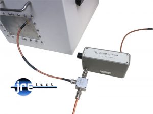
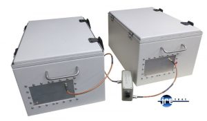 Two JRE 1812 test enclosures interconnected with antennas and step attenuator. Boxes are closed so all signals between the enclosures have to pass through the step attenuator.
Ground Rules
First, we need to understand the process of an antenna radiating — or transmitting — an RF signal. By reciprocity, an antenna functions the same electrically when receiving as when transmitting. So while we will generally describe things from the transmitter side, understand that the same effects apply in reverse when receiving. We will also stay at a basic level in describing some principles and take some liberties in how we define and explain things — the goal of this paper is to help shed light into the effects and expectations when using small antennas within a shielded test enclosure environment.
We will call the device that creates the RF signal a "transmitter" and the device that captures and utilizes the RF signal a "receiver." Simple enough.
Matching and Impedance
The antenna takes the RF signal from the transmitter and "launches" it out into the air. A coaxial cable connects the transmitter to the antenna and forms an important part of the transmission system. You have likely heard terms like coaxial cable impedance, SWR, reflected power, forward power, and match — these all describe the efficiency, operation, and general characteristics of the antenna and transmitter system overall.
The basic idea is straightforward: you want to maximize the power from the transmitter, make sure all of it couples into the coaxial cable, travels to the antenna, and gets fully radiated — with nothing getting reflected or "bounced" back to the transmitter. This is why you will commonly see 50 ohm cables, 50 ohm antennas, and 50 ohm transmitters. Everything in the chain wants to be 50 ohms.
The antenna has a tough job. It must match the impedance of the coaxial cable (50 ohms) to the much higher impedance of free space (377 ohms). There are a variety of methods used to achieve this, but one of the most common antennas is the quarter-wave. Its advantage is that its feed point impedance is naturally very close to 50 ohms. In its simplest form, it is just a piece of wire that is one-quarter wavelength long at the operating frequency. There are many variations of this simple antenna, but it is the most common type used in test enclosure work, and thus the best baseline to compare against others.
If an antenna must operate over a wide range of frequencies, obviously a single quarter-wavelength wire cannot be correct at all frequencies simultaneously. There are many techniques to achieve a proper match across a wide frequency range — extra matching components, multiple antenna elements of differing dimensions, or lossy broadband designs. If your testing involves widely spaced frequencies, the antenna selection will be more involved.
For more information on the antennas available from JRE Test, see our antenna product page.
Antenna Radiation — What to Expect Inside a Test Enclosure
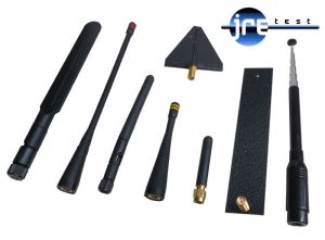
So far we have become a bit familiar with antennas and their connection to transmitters, but what can we actually expect for signal levels inside a test enclosure? We made some measurements at popular wireless frequencies using common quarter-wave antennas as well as the JRE BBA-1 broadband antenna. Signals were applied to a transmitting antenna and a nearby receiving antenna was used to measure the received signal strength. Knowing the applied transmitter power and then the measured received signal power, we can easily calculate the "path loss" between the transmit and receive antenna combination.
In the cases described below, we used antennas placed approximately 10 inches (25 cm) apart, polarized in the same orientation.
A word on polarization: this is a term used to describe the geometry of the emitted wave from an antenna. A vertically oriented antenna produces vertically polarized radiation, while a horizontal antenna produces horizontally polarized radiation. Cross-polarization between the transmit and receive antennas can result in severe signal degradation, but in the confines of a small test enclosure this effect is minimized — the reflections inside the enclosure scramble things considerably. Bear in mind that there will be variations in signal levels depending upon antenna placement, polarization, and distance between antennas, but these measurements are accurate enough to get a general handle on what to expect.
For repeatable measurements, one can use a firmly fixed test fixture to ensure the test device is always placed in the exact same position each time within the test enclosure.
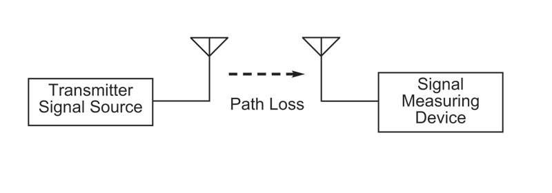
Path Loss Measurement Setup
The setup is straightforward: a signal source is set at 0 dBm and connected via coaxial cable to the transmitting antenna inside the test enclosure. A receiving antenna, also inside the enclosure, is connected to a spectrum analyzer. The indicated signal is read in dBm from the spectrum analyzer. The difference between the 0 dBm applied signal and the received signal is the path loss.
Results at Popular Wireless Frequencies Using Quarter-Wave Antennas
| Frequency | Path Loss |
|---|---|
| 433 MHz | 30 dB |
| 916 MHz | 40 dB |
| 2.4 GHz | 30 dB |
Using the BBA-1 broadband antenna, signal levels were approximately 25 dB lower than the quarter-wave antenna. This is the price we pay for having an extremely broadband antenna — more loss but the ability to operate across almost 10 octaves of frequency range without swapping antennas. The BBA-1 is intentionally "lossy" — it looks like a terminated transmission line but is deliberately leaky. This lossiness actually makes it less affected by its environment inside the enclosure, which is a real advantage when nearby objects are affecting antenna match. See our paper on understanding antenna performance inside a test enclosure for more on near-field effects.
Putting This Knowledge to Work
Knowing the path loss allows us to estimate the power needed in order to radiate a sufficiently strong signal to a device inside the test enclosure. Knowing the required signal level for proper operation of a receiving device, along with the path loss, we can set our signal source to the correct level.
Example 1 — Testing a Receiver:
We have a wireless doorbell receiver that operates at 433 MHz and engineering has designed this receiver to have a sensitivity of –100 dBm. This is the minimum power required for the receiver to operate correctly. Knowing that the path loss using quarter-wave antennas is 30 dB, we can calculate that the external signal source must put out –70 dBm into the transmit antenna inside the test enclosure for the receiver to "hear" it.
If we wish to do a sensitivity check on a series of these devices — as you might find in a production final test situation — we select a suitable "gold standard" device (one that is properly operating to spec), affix it to an immovable and secured test fixture inside the enclosure, adjust our external signal source to the correct level, and test our devices. The immovable test fixture keeps everything in the same position and makes the test repeatable. We use a gold standard device to calibrate the system since the path loss figures above are typical figures, not exact for each and every device and test setup. The figures get us quickly into the ball park.
Example 2 — Testing a Transmitter:
We have a wireless doorbell button transmitter that operates at 433 MHz at an output power of 0 dBm. Using a spectrum analyzer or calibrated receiver with a quarter-wave antenna inside the test enclosure, we know the path loss is 30 dB. So if we measure –30 dBm from this antenna, we know the transmitter inside is radiating the correct 0 dBm signal. Once again, we calibrate with a gold standard device mounted in an immovable fixture, and then production units can be repeatedly tested thereafter. The path loss figure gives us a good starting point as to what to expect when setting up.
Using the BBA-1 Broadband Antenna for Multi-Frequency Testing:
Let's say you are testing devices that operate over a wide frequency range. In this case the BBA-1 offers wide frequency response — 1 MHz to over 6 GHz — however at a greater path loss. You should figure in another 25 dB of loss compared to the quarter-wave figures above. For example, in the 433 MHz doorbell scenario, the path loss would be the quarter-wave figure (30 dB) plus the 25 dB extra from the BBA broadband antenna — a total of 55 dB path loss.
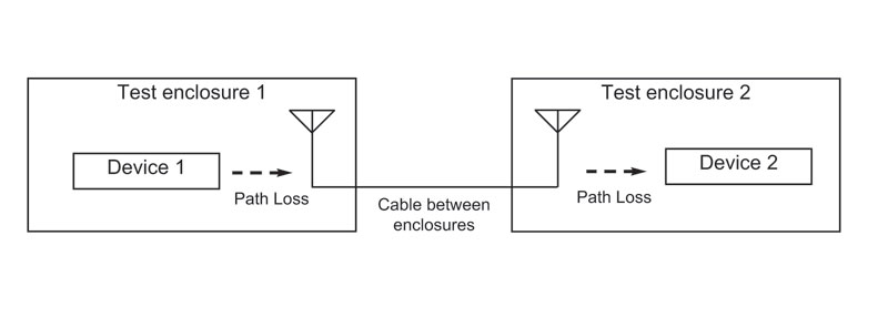
Transmitting From One Test Enclosure to Another
In some instances you would like to have one wireless device "talk" to another as you would find in an actual wireless environment. You would have one device inside one test enclosure and the other device inside another test enclosure, with a coaxial cable linking the antennas inside each enclosure.
Using our wireless doorbell example: there would be 30 dB path loss from Device 1 to the antenna in Enclosure 1, and again 30 dB path loss from the antenna to Device 2 inside Enclosure 2 — for a total of 60 dB path loss (ignoring the small loss in the coaxial cable connecting the two enclosures). If Device 1 puts out 0 dBm, this means there will be –60 dBm of signal arriving at Device 2.
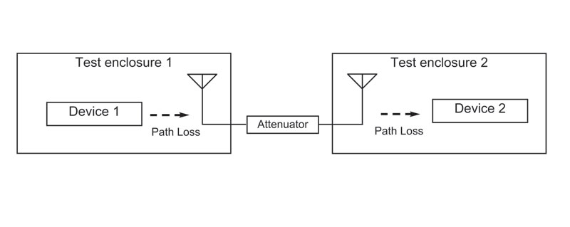
 Simulating Distance With an Attenuator
Now here is where it gets interesting. Let's say we wish to simulate more distance between the two devices. We can do this by adding a step attenuator in line between the antennas on the two test enclosures. By varying the attenuation, we can make the signal weaker between the two devices — effectively simulating greater and greater distance, all while sitting on the bench.
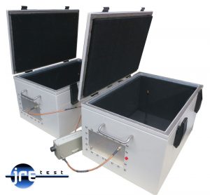 Two JRE 1812 test enclosures interconnected with antennas and step attenuator.
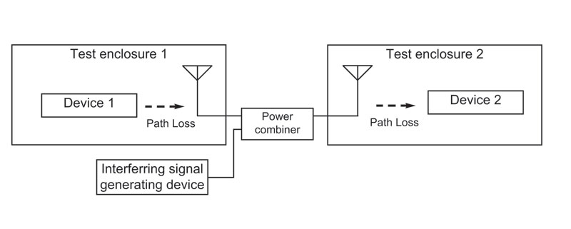
Adding Interfering Signals
We can make the test even more real-world by adding in interfering signals such as noise, other RF signals, or anything else you can dream up. To do this, add a simple power combiner and introduce the interfering signal through one of its ports. The antenna inside the enclosure will now radiate not only the desired signal but also the interfering signal you introduced. If you are introducing an interfering signal at a far different frequency from the desired signal, the broadband BBA-1 antenna is especially useful because of its wide bandwidth.
Mini-Circuits makes a broad line of low cost power combiners — just select a suitable device based upon your frequency of interest and the number of ports needed for however many interfering signals you wish to add. As an example, the Mini-Circuits ZFSC-2-5 is a two-way, zero-degree (combines in-phase) device good from 10 to 1500 MHz — ideal for our wireless doorbell example. You can combine the power combiner with a step attenuator to independently control the desired signal level while adding in one or more interfering signals.
 Using a power combiner to add in an extra interfering signal and a step attenuator to adjust desired signal. Combined signals are then fed into the shielded test enclosure.
Final Thoughts
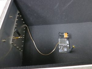
The above tests were performed using JRE 1812 test enclosures with a simple I/O plate and bulkhead SMA connectors. A variety of different antennas and devices were used in measuring the path loss figures.
This paper should help you understand the techniques used to radiate signals into and out of an RF shielded test enclosure, along with some general values for expected path loss at different frequencies. There is nothing complex about setting up such tests, and even simulating real-world operation with interfering signals and greater distance between devices using an attenuator is straightforward.
For related reading, see Taking the Mystery Out of RF Wireless Testing, How to Select and Configure an RF Shielded Test Enclosure, and Understanding Antenna Performance Inside an RF Shielded Test Enclosure.
For information on antennas, visit our antenna product page. For questions on any of the techniques described here, contact JRE Test technical directly.