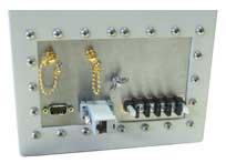
 Sending signals into and out of the RF Shielded test enclosure presents some contradictory issues. After all, the enclosure is designed to shield out any RF signals from passing across its shielded walls - think of it as a barrier which doesn't allow anything to pass across. But, what good is the enclosure if we cannot perform any tests on the device which is inside? We need to measure the device's response to our stimulus and this means we will need some sort of way of getting our desired test stimulus signal across the enclosure's barrier. JRE Test offers a variety of high performance filtered I/O adapters for popular data signal formats such as USB and Ethernet and even a Universal Filtered Interface for a wide variety of signals such as: Automotive Ethernet, CAN, BroadR, 100/1000BaseT1, FlexRay, 802.3, LVDS, CML, RS232/422/485, Audio, TRS/XLR, and 20mA current loop. To complete the selection we also offer general purpose simple capacitive filtered DB style connectors.
Interfacing these data formats requires thoughtful consideration of the data speeds and RF frequency of the device under test. In most cases, a proper filtered interface should be selected for ease of use and reliable, proven performance. If you have a connector or device not served by one of our specifically designed interface filters, the UFI-1 universal filtered interface uses handy screw terminals for connection to virtually any connector.
To explore the ramifications on using simple capacitance filtered DB style connectors when passing data signals, let take a deeper look at what's involved. These test signals are some sort of high speed data and actually are nothing more than a form of modulated RF signal! Here's the problem: we wish to allow serial data (which can be considered a form of modulated RF energy) into and out of the enclosure while still stopping undesired RF signals from entering or exiting the box. If our data signal is fairly slow, we can use a simple capacitive filtered connector such as the popular DB-9 style serial connector. Internally, this connector has feed-through capacitors on all pins. These capacitors appear electrically as capacitance from the data pin to ground. Their performance at RF frequencies is excellent, thus their popularity. 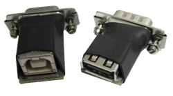 Simple PCB adapters can be used to connect to the DB-9 and adapt it to USB style connectors, 3.5mm audio connectors or even RJ style LAN/Phone connectors.
Capacitance values are available ranging from 1000 pf to as small as 10 pf. Note that this capacitance will be 'hung' directly on the data line and your device will be driving not only your desired interface device but also this capacitance to ground. While this capacitance will load the data lines, there is a trade-off regarding acceptable serial data attenuation/distortion and acceptable RF filtering attenuation.
For example, 9600 baud RS-232 serial data results in a serial data stream of approximately 19.2 KHz, so hanging a 1000 pf capacitor across one of the data lines would in effect load the line with 8.3 K ohms to ground. this was calculated using the formula for capacitive reactance:
![]()
Where: XC is capacitive reactance in ohms, f is frequency in Hertz, and C is capacitance in farads. In most cases this extra loading will not result in any appreciable attenuation or distortion of the 9600 baud data. We can use this same sort of reasoning when we consider other serial data interface filtering, making a reasonable tradeoff between amount of capacitance and data speed. In general we should use the most capacitance possible while still maintaining an acceptable amount of loading on the data lines, this provides the maximum amount of RF filtering.
Let's examine this effect a bit further. Note that the capacitance appears to your device as a load on your data line and also that your device has a driving impedance - called it's source impedance. This source impedance combines with the filtering capacitance and forms a simple R-C low pass filter.
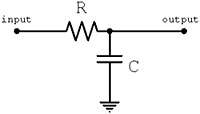
If the driving source impedance is low, the capacitance effect will be less than if the source impedance is high. Look at the R-C filter as a simple resistive voltage divider with the source impedance being the series R component and the filtering capacitance being the parallel C component. As we saw earlier, the capacitor has an impedance which is a function of the frequency applied to it, in accordance with the reactance formula below:
![]()
As we noted above, a 1000pf capacitor has an impedance of 8.3K ohm at 19.2KHz, so if the device has a source impedance of 8.3K also, the net effect of the DB-9 connector's filtering is a reduction of the signal by one-half! (the voltage divider having equal resistances of 8.3K dividing the signal by 1/2).
We just looked at an RS-232 data signal, what about video? Video is generally understood to be composed of frequency components up to 4 MHz and usually 75 ohm as the impedance of the devices used with it. Thus the source impedance is 75 ohms and any video passing through a filtered connector will have its capacitance 'hung' across the video line. If we use a 1000pf filtered connector, we can analyze how much attenuation this capacitance will have for the video. The capacitor's impedance at 4 MHz will be: 1/((2*pi)(4e6)(1000e-12) [note the scientific notation: 4e6 means 4 times 10 to the 6th power: 4,000,000. It is easier to use scientific notation rather than mess with all those zeros!] after calculating, we see that the capacitor (at 4 MHz) looks like a 39.8 ohm resistor. Combined with the 75 ohm source impedance, we see that the final signal coming across this filtered pin is reduced by about 2/3rds, leaving us with only a third of the original signal. Also note that this is at 4 MHz - at lower frequencies, the loss is less, so we end up with a severely rolled-off response!
This essay is not meant to be the end all in data filtering for RF Shielded test enclosures, but it does serve to make an engineer appreciate the nuances of getting test signals across the RF shielded barrier. It is nothing more than basic 2nd year theory from your electronic engineering education!