Overview
Each generation of wireless technology pushes operating frequencies higher. Early cellular and WiFi operated in the UHF range of 800 MHz to 2.6 GHz. WiFi 5 and WiFi 6 moved into the 5 GHz band. WiFi 6E added the 6 GHz band. And 5G NR (New Radio) introduced two distinct frequency ranges:
5G FR1 (sub-6 GHz): 410 MHz to 7.125 GHz — an extension of familiar cellular bands, well within the operating range of standard JRE Test enclosures.
5G FR2 (millimeter wave): 24.25 GHz to 52.6 GHz — a major step up in frequency that places significant new demands on RF shielding. The frequencies most commonly deployed today are n257 (26.5–29.5 GHz), n258 (24.25–27.5 GHz), n260 (37–40 GHz), and n261 (27.5–28.35 GHz).
Standard JRE Test enclosures are specified for use up to 6 GHz, providing -100 dB isolation from DC to 1 GHz, -95 dB to 3 GHz, and -85 dB to 6 GHz. This covers the vast majority of wireless testing — WiFi, Bluetooth, cellular through 4G LTE, Zigbee, LoRa, and 5G FR1 all fall within this range. But for testing devices operating at 5G FR2 frequencies or other microwave applications above 6 GHz, the standard enclosure's isolation degrades significantly, and an upgraded approach is needed.
Why Higher Frequencies Are Harder to Shield
An RF test enclosure works on the principle of a Faraday cage — a continuous conductive enclosure that blocks external RF radiation from entering, and contains internal radiation from escaping. The key word is "continuous." Any interruption in that conductive barrier — a door gasket, an I/O plate seam, a hardware attachment point, a ventilation port — is a potential leakage path.
At lower frequencies, these interruptions are electrically small relative to the wavelength, and their effect on shielding is minimal. But as frequency increases, wavelength decreases, and gaps that were inconsequential at 2 GHz become significant leak paths at 28 GHz. To put numbers on this:
At 1 GHz, one wavelength is 300 mm (about 12 inches) — a 1 mm gap is 1/300th of a wavelength and causes negligible leakage.
At 6 GHz, one wavelength is 50 mm (about 2 inches) — a 1 mm gap is 1/50th of a wavelength. Still small, but becoming relevant.
At 28 GHz, one wavelength is 10.7 mm (about 0.4 inches) — a 1 mm gap is nearly 1/10th of a wavelength. At this point, even very small gaps become effective radiating slots.
At 40 GHz, one wavelength is 7.5 mm (about 0.3 inches) — a 1 mm gap is 1/7.5th of a wavelength. Virtually any mechanical discontinuity will leak.
This is why an enclosure that provides 100 dB of isolation at 2 GHz may provide only 35 dB at 28 GHz without additional treatment — the construction that seals effectively at longer wavelengths simply cannot address the much shorter wavelengths without specific attention to every potential gap.
The JRE Microwave (MW) Upgrade
To address microwave-frequency testing, JRE Test developed an enhanced shielding treatment that extends enclosure performance to 28 GHz at greater than -85 dB isolation. This is available as an option on any standard JRE Test enclosure, designated by adding "MW" to the model number (for example, JRE-1812MW).
The MW upgrade adds a conductive fabric gasket at all critical seam locations — the lid-to-body interface, the I/O plate perimeter, and hardware attachment points. The existing robust mechanical construction of the standard enclosure was already very tight; the MW upgrade focuses specifically on the discontinuities that become significant at shorter wavelengths. Extensive redesign of the enclosure body itself was not needed.
The MW upgrade is priced at $480 per enclosure over the standard price. When using an MW-rated enclosure, all I/O filters must also be MW-rated to maintain system isolation at microwave frequencies — the MW filter surcharge is $80 per single filter section ($160 for dual filters). We will discuss why this matters in the test results below.
Lab Test Results
To quantify the effect of the MW upgrade, we tested a stock JRE 1812 and an MW-upgraded JRE 1812MW at both 2.45 GHz and 28 GHz, using two I/O plate configurations: a completely blank plate (to isolate the enclosure's inherent performance) and a plate with a single JRE LAN-1 Ethernet filter installed.
Enclosure with blank I/O plate (no filters):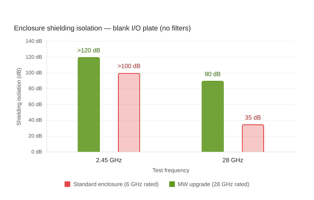
The standard enclosure provides excellent isolation at 2.45 GHz but only 35 dB at 28 GHz — enough to notice a reduction in external interference, but insufficient for most serious testing. The MW upgrade brings 28 GHz isolation to greater than 90 dB, a dramatic improvement. As an added benefit, the MW treatment also improves isolation at lower frequencies — at 2.45 GHz, isolation exceeded the measurement capability of the test equipment at -120 dB.
Enclosure with JRE LAN-1 Ethernet filter installed: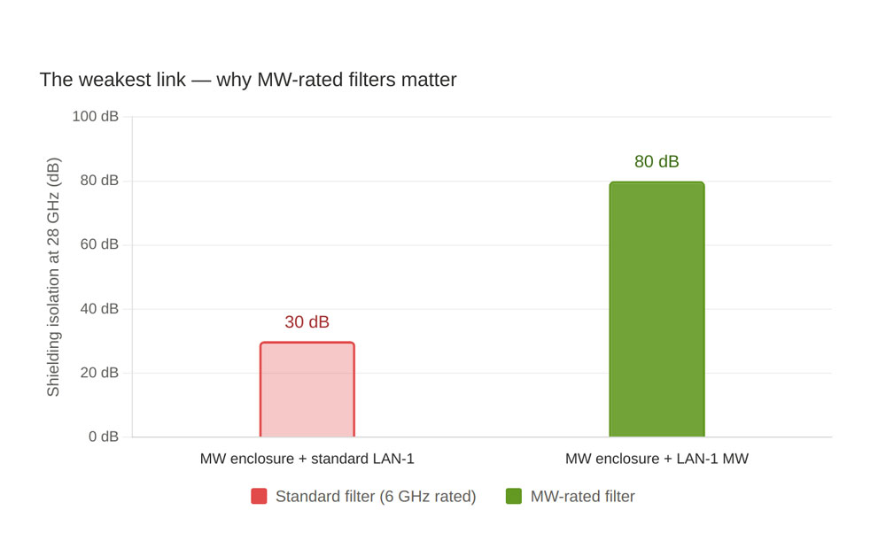
This result illustrates a critical point: the system is only as good as its weakest link. Pairing an MW-rated enclosure with a standard (6 GHz) I/O filter negates most of the enclosure upgrade — the standard LAN-1 leaks at 28 GHz, providing only 30 dB of isolation regardless of how well the enclosure itself is sealed. Replacing the standard LAN-1 with the MW-rated LAN-1MW restored system isolation to 80 dB at 28 GHz. When ordering an MW enclosure, always order MW-rated I/O filters to match. There is no benefit to upgrading the enclosure without also upgrading the filters.
RF Connectors for Microwave Testing
At frequencies above 18 GHz, standard SMA connectors begin to exhibit moding (higher-order propagation modes) that degrades performance. For testing at 5G FR2 frequencies (24–40 GHz), we recommend 2.92 mm (K-type) bulkhead feedthrough connectors, which are rated to 40 GHz. These are available as an option on any I/O plate configuration.
For testing at standard frequencies up to 18 GHz, SMA bulkhead connectors remain the standard choice and perform well. BNC and Type N connectors are suitable for lower-frequency applications.
Antennas at Microwave Frequencies
Inside a test enclosure at microwave frequencies, antenna selection requires the same near-field considerations discussed in our whitepaper Understanding Antenna Performance Inside an RF Shielded Test Enclosure, but with additional attention to frequency coverage. The JRE BBA-1 broadband antenna is specified to beyond 6 GHz. For higher frequencies, the JRE ANT-211 log-periodic covers 2–11 GHz. For 5G FR2 testing at 24–40 GHz, a suitable antenna for the frequency range must be used — contact us to discuss antenna options for your specific frequency band.
At microwave frequencies, the RF absorbing foam inside the enclosure becomes more effective (higher frequencies are more readily absorbed), which is beneficial for reducing standing waves and reflections.
Testing Beyond 28 GHz
The MW upgrade is specified and tested to 28 GHz at greater than -85 dB isolation. We have not formally characterized enclosure performance beyond 28 GHz, and we cannot offer concrete isolation specifications at 40 GHz or 60 GHz. However, for customers who need to test at these higher frequencies, the MW gasket treatment and 2.92 mm connectors will provide the best available performance from a benchtop enclosure. The physics of wavelength vs. gap size means that performance will continue to decrease as frequency increases beyond 28 GHz, but the MW treatment addresses the dominant leak paths and will outperform a standard enclosure by a wide margin at any frequency.
If your testing requires operation above 28 GHz, contact us to discuss your specific requirements — we can advise on the best configuration and set realistic expectations for the isolation you can achieve.
Ordering the MW Upgrade
The MW upgrade is available on any standard JRE Test enclosure. To order:
Specify "MW" when ordering the enclosure (for example, JRE 1812MW instead of JRE 1812). Cost: $480 over the standard enclosure price.
Specify "MW" on all I/O filters (for example, LAN-1MW instead of LAN-1). Cost: $80 per single filter section, $160 per dual filter section.
If you are using 2.92 mm RF connectors, specify these on the I/O plate configuration. Be aware these connectors are quite expensive (over $125 each) so if you do not need the their improved VSWR spec, standard SMA may be used. There is no difference in either connector's shielding isolation.
It is much easier and more cost-effective to order the MW upgrade at the time of initial purchase than to retrofit an existing enclosure. We build and final-test the chamber with the MW treatment and MW-rated filters in place, ensuring the complete system meets specification before it ships.
Do You Need the MW Upgrade?
For most wireless testing — WiFi (2.4/5/6 GHz), Bluetooth, cellular through 4G LTE, Zigbee, LoRa, GPS, and 5G FR1 (sub-6 GHz) — the standard enclosure provides excellent performance and the MW upgrade is not needed.
The MW upgrade is recommended when your device operates at frequencies above 6 GHz, including 5G FR2 (mmWave), point-to-point microwave links, radar systems, satellite communications in Ka-band (26.5–40 GHz), automotive radar (76–81 GHz, noting that our tested range extends to 28 GHz), and any application where you need the highest possible isolation at frequencies up to 28 GHz.
If you are unsure whether you need the MW upgrade, the simplest question is: does your device operate above 6 GHz? If yes, you want the MW upgrade. If no, the standard enclosure is the right choice. And as the test data shows, the MW upgrade also provides a measurable improvement at conventional frequencies — so if your testing requires the absolute maximum isolation regardless of frequency, the MW upgrade delivers.
Further Reading
For general guidance on selecting and configuring an enclosure: How to Select and Configure an RF Shielded Test Enclosure.
For understanding how I/O filters affect system isolation: The Effect of Adding Multiple I/O Filters to a Test Enclosure.
For antenna considerations inside test enclosures: Understanding Antenna Performance Inside an RF Shielded Test Enclosure.
For measuring and verifying your enclosure's shielding isolation: Measuring and Verifying the Shielding Isolation of an RF Shielded Test Enclosure.
For an overview of RF testing concepts: Taking the Mystery out of RF Wireless Testing.
Browse the complete enclosure catalog or the full range of I/O interfaces.